Media conditioning & climate testing
Media or air conditioning (T, rh, p) is used as a test method for environmental simulation or temperature control of the ambient air of components from various industries (e.g. HVAC-R, automotive industry). Test items are tested according to standards under the required environmental conditions. The temperature ranges start at -20 °C and usually end at around 60 °C. Depending on the application, we can offer you customer-specific temperature, pressure or humidity ranges.
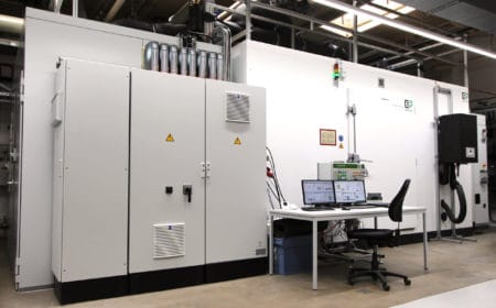
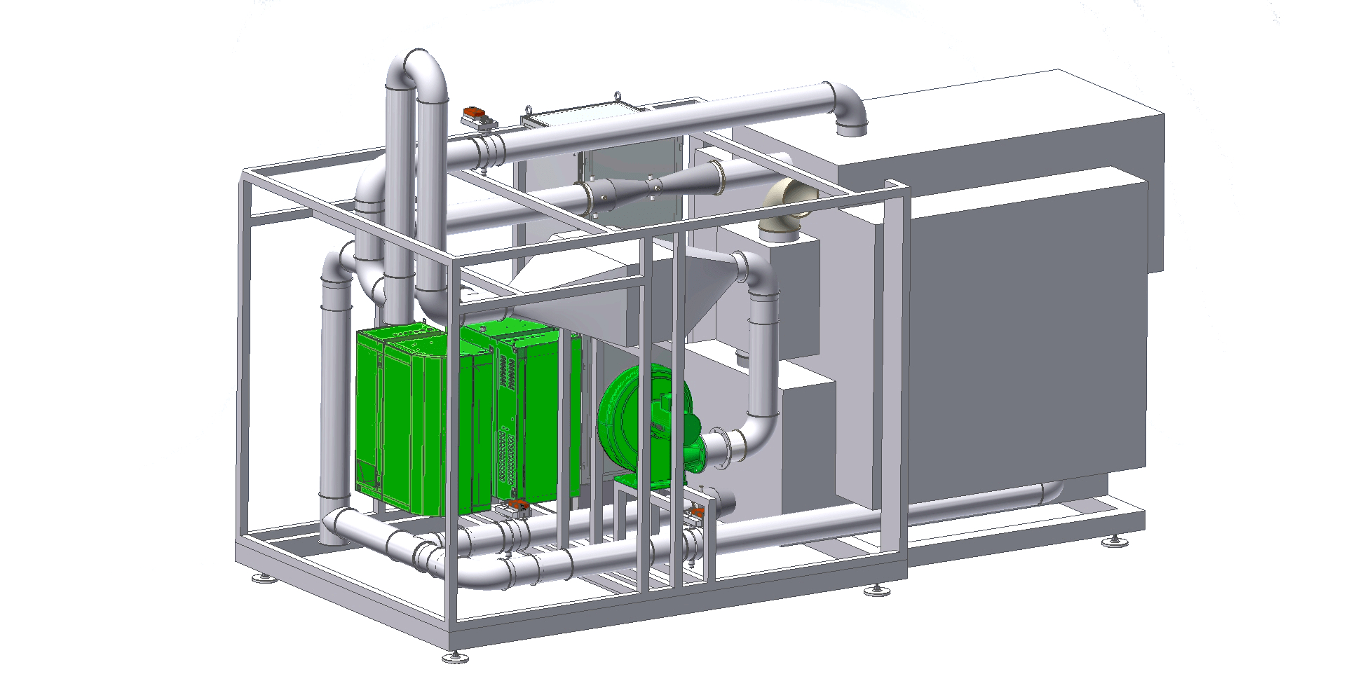
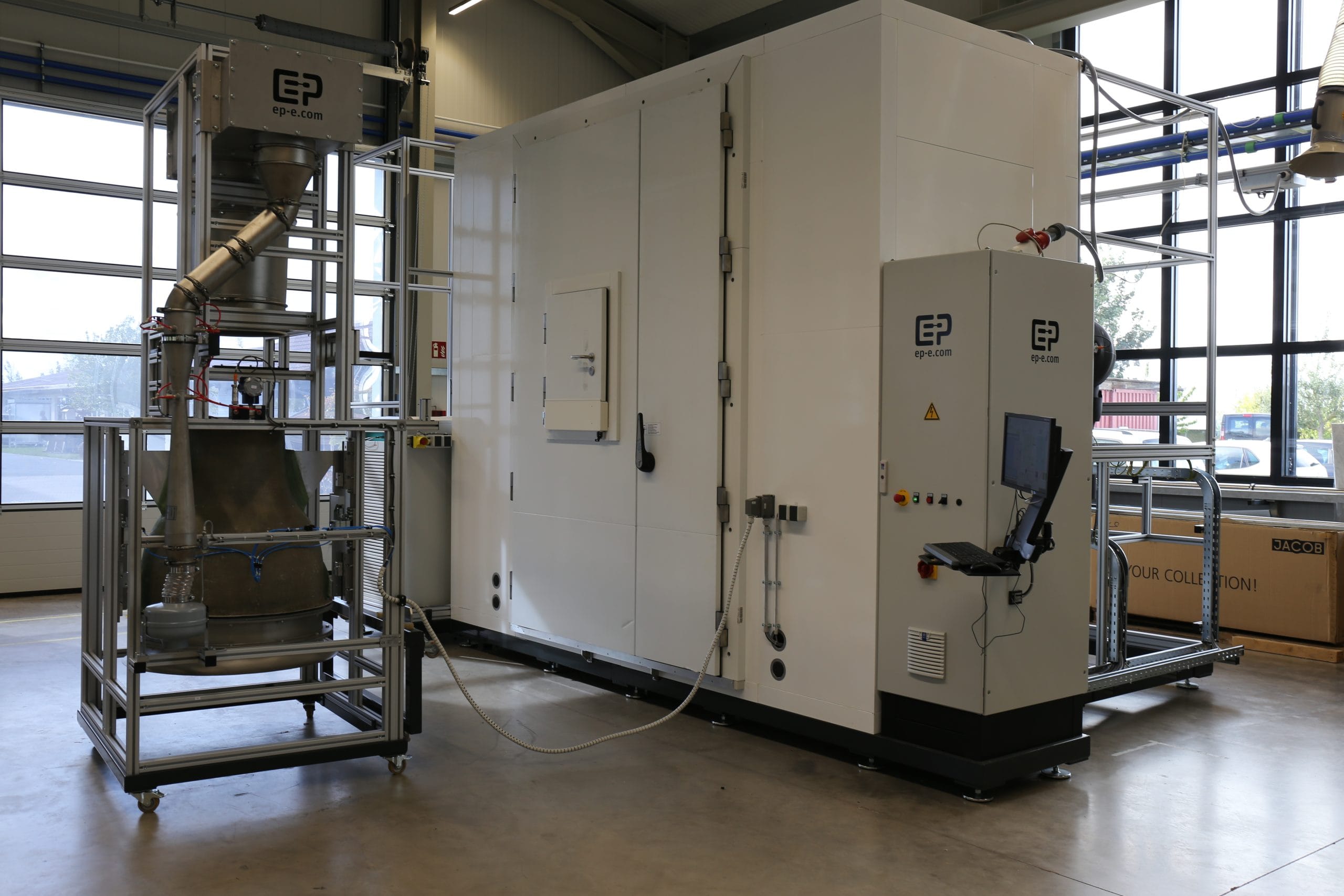
Current test systems on the market that are used to test air / water heat pumps, for example, are climatic chambers with a cooling, heating and humidification unit attached to the roof. The disadvantage of this concept is that a homogeneous temperature and humidity distribution cannot be set in the cube-like room. Based on test engineering concepts in the automotive industry, EPE developed a concept in which the air flows in a closed circuit (loop design). This is blown into and out of the chamber via a flow straightener. The temperature control (cooling, heating) and humidification takes place outside the chamber. The result of this concept is a very excellent homogeneous temperature and humidity distribution. In addition, it is possible to set and vary the air flow depending on the standard conditions in the loop.
Test benches for environmental testing
Test methods
- Simulation of the environmental conditions of the components to be tested
- Conditioning – controlling, regulating, measuring:
Water (temperature, pressure, volume, density)
Air (temperature, pressure, volume, density, humidity)
Features
Environmental simulation
Temperature and humidity conditioning
Closed Loop Design
Compliance with the required test standards
Specification
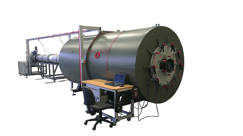
| Heat pump test bench | Purge air test bench | Gas heating test bench | Fan and blower test benches | HVAC acoustic test bench | Flow channel for room air sensors | |
|---|---|---|---|---|---|---|
| Test item | Heat pump | Decentralized ventilation units | Heat exchanger of the gas heating systems | Fan and blowers | HVAC modules | Room air sensors |
| Standard | DIN EN 14511 | DIN EN ISO 13141-8 | — | DIN EN ISO 5801 or AMCA 210 | — | — |
| Medium | Air | Air | Water | Air | Air | Air |
| Temperature control | -25…+50 °C | 7…21 °C (expandable) | 0…120 °C | — | — | 10…40 °C |
| Humidity control | 10…92 % r.h. | 10…92 % r.h. | — | — | — | 5…80 % r.h. |
| Flow or velocity control | 1000…7000 m³/h | 20…200 m³/h | — | 1… 100,000 m³/h | 1…1000 m³/h | 0.3…0.5 m/s |
| Key Benefit, Application | Closed-loop design for dynamic, uniform T and H control and an optimized safety concept (ATEX Zone 2), a wide range of expansion levels possible | Determination of thermal performance indicators of alternating ventilation devices | Endurance test of gas heaters (2… 45 kW); different load conditions and temperature changes (e.g. shock temperature changes) | Characteristic curve recording of fans and blowers | Testing and determination of characteristic curves of HVAC modules | Testing room sensors under conditioned conditions (air velocity, temperature, humidity, CO2 content) |


